Simulating an interrupt
Adding an interrupt handler
The application—a brief description
Writing an interrupt handler for ARM7TDMI
Writing an interrupt handler for Cortex-M3
Setting up the project
Setting up the simulation environment
Defining a C-SPY setup macro file
Setting C-SPY options
Building the project
Starting the simulator
Specifying a simulated interrupt
Setting an immediate breakpoint
Simulating the interrupt
Executing the application
Using macros for interrupts and breakpoints
* In this tutorial an interrupt handler for a serial port is added to the project. The Fibonacci numbers are read from an on-chip communication peripheral device (UART).
* This tutorial will show how to write an interrupt function for ARM7TDMI and for Cortex-M3. The tutorial will also show how to simulate an interrupt, using the features that support interrupts, breakpoints, and macros. Notice that this example does not describe an exact simulation; the purpose is to illustrate a situation where C-SPY® macros, breakpoints, and the interrupt system can be useful to simulate hardware.
* This tutorial assumes that you are familiar with the basics of the IAR Embedded Workbench® IDE described in the previous tutorial tutorials.
* Note that interrupt simulation is possible only when you are using the IAR C-SPY Simulator.
Adding an interrupt handler
This section will demonstrate how to write an interrupt in an easy way. It starts with a brief description of the application used in this project, followed by a description of how to set up the project.
The application—a brief description
The interrupt handler will read values from the serial communication port receive register (UART), UARTRECEIVE. It will then print the value. The main program enables interrupts and starts printing periods (.) in the foreground process while waiting for interrupts.
Note: In this tutorial, UARTRECEIVE refers to the receive register on the ARM7TDMI-based dummy device arm7 and the Cortex-M3-based dummy device cm3, respectively. To follow this tutorial and simulate the interrupt in the C-SPY simulator, you should use the register that is suitable for the core and device you are using.
Writing an interrupt handler for ARM7TDMI
The following lines define the interrupt handler used in this tutorial (the complete source code can be found in the file Interrupt.c in project4 supplied in the arm\tutor directory):
/* define the IRQ handler */
__irq __arm void IRQ_Handler( void )
The __irq keyword is used for directing the compiler to use the calling convention needed for an interrupt function. The __arm keyword is used for making sure that the IRQ handler is compiled in ARM mode. In this example only UART receive interrupts are used, so there is no need to check the interrupt source. In the general case however, when several interrupt sources are used, an interrupt service routine must check the source of an interrupt before action is taken.
For detailed information about the extended keywords used in this tutorial, see the IAR C/C++ Development Guide for ARM®.
Writing an interrupt handler for Cortex-M3
On Cortex-M3, an interrupt service routine enters and returns in the same way as a normal function, which means no special keywords are required.
In the Interrupt.c file in the Project4CM3 project, the interrupt function UART_Handler is provided. Note that when you add an interrupt function for Cortex-M devices, you must also add the name of that function in the interrupt vector table. You do this in the system startup code cstartup.s. For this tutorial, a reference to the UART_Handler function is already provided in __vector_table, which you can find in the file CstartupCM3.s.
For more information about how to write device-specific interrupt functions for Cortex-M, see the IAR C/C++ Development Guide for ARM®.
Setting up the project
1
Add a new project—project4—to the workspace tutorials used in previous tutorials.
2
Add the files Utilities.c and Interrupt.c to it.
3
In the Workspace window, select the project level node and choose Project>Options. Select the General Options category, and click the Target tab. Choose ARM7TDMI or Cortex-M3 from the Core drop-down menu.
4
For ARM7TDMI, select the C/C++ Compiler category, and click the Code tab. Select the option Generate interwork code.
5
Next you will set up the simulation environment.
Setting up the simulation environment
The C-SPY interrupt system is based on the cycle counter. You can specify the amount of cycles to pass before C-SPY generates an interrupt.
To simulate the input to UART, values are read from the file InputData.txt, which contains the Fibonacci series. You will set an immediate read breakpoint on the UART receive register, UARTRECEIVE, and connect a user-defined macro function to it (in this example the Access macro function). The macro reads the Fibonacci values from the text file.
Whenever an interrupt is generated, the interrupt routine reads UARTRECEIVE and the breakpoint is triggered, the Access macro function is executed and the Fibonacci values are fed into the UART receive register.
The immediate read breakpoint will trigger the break before the processor reads the UARTRECEIVE register, allowing the macro to store a new value in the register that is immediately read by the instruction.
This section will demonstrate the steps involved in setting up the simulator for simulating a serial port interrupt. The steps involved are:
*
Defining a C-SPY setup file which will open the file InputData.txt and define the Access macro function
*
*
*
*
*
Note: For a simple example of a system timer interrupt simulation, see the C-SPY® Debugging Guide for ARM®.
Defining a C-SPY setup macro file
In C-SPY, you can define setup macros that will be registered during the C-SPY startup sequence. In this tutorial you will use the C-SPY macro file SetupSimple.mac, available in the arm\tutor directory. It is structured as follows:
First the setup macro function execUserSetup is defined, which is automatically executed during C-SPY setup. Thus, it can be used to set up the simulation environment automatically. A message is printed in the Log window to confirm that this macro has been executed:
execUserSetup()
{
__message "execUserSetup() called\n";
Then the file InputData.txt, which contains the Fibonacci series to be fed into UART, is opened:
_fileHandle = __openFile( "$PROJ_DIR$\\InputData.txt", "r" );
After that, the macro function Access is defined. It will read the Fibonacci values from the file InputData.txt, and assign them to the receive register address:
Access()
{
__message "Access() called\n";
__var _fibValue;
if( 0 == __readFile( _fileHandle, &_fibValue ) )
{
UARTRECEIVE = _fibValue;
}
}
You must connect the Access macro to an immediate read breakpoint. However, this will be done at a later stage in this tutorial.
Finally, the file contains two macro functions for managing correct file handling at reset and exit.
For detailed information about macros, see the C-SPY® Debugging Guide for ARM®.
Next you will specify the macro file and set the other debugger options needed.
Setting C-SPY options
1
To set debugger options, choose Project>Options. In the Debugger category, click the Setup tab.
2
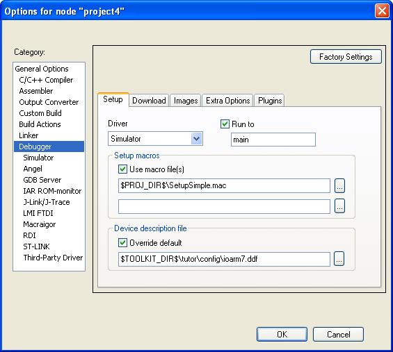
Use the Use macro file browse button to specify the macro file to be used:
SetupSimple.mac
Alternatively, use an argument variable to specify the path:
$PROJ_DIR$\SetupSimple.mac
For reference information about argument variables, see the IDE Project Management and Building Guide for ARM®.
3
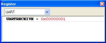
Next, you will specify the device description file. This file makes it possible to view the value of UARTRECEIVE in the Register window and provides the interrupt definitions that are needed by the interrupt system.
For ARM7TDMI, set the Device description file option to $TOOLKIT_DIR$\tutor\config\ioarm7.ddf.
For Cortex-M3, set the Device description file option to $TOOLKIT_DIR$\tutor\config\iocm3.ddf.
4
Select Run to main and click OK. This will ensure that the debug session will start by running to the main function.
The project is now ready to be built.
Building the project
1
Alternatively, click the Make button on the toolbar. The Make command compiles and links those files that have been modified.
Starting the simulator
1
Click the Download and Debug button to start C-SPY and run the project4 or the project4CM3 project.
The Interrupt.c window is displayed (among other windows). Click in it to make it the active window.
2
Specifying a simulated interrupt
Now you will specify your interrupt to make it simulate an interrupt every 2000 cycles.
1
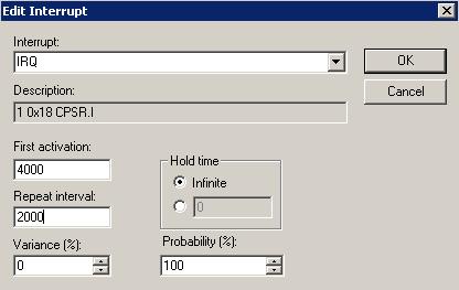
Choose Simulator>Interrupt Setup to display the Interrupt Setup dialog box. Click New to display the Edit Interrupt dialog box:
Make these settings for your interrupt:
 
The interrupt definition that the simulator uses to be able to simulate the interrupt correctly.
Specifies the first activation moment for the interrupt. The interrupt is activated when the cycle counter has passed this value.
Repeat interval
Specifies probability. 100% specifies that the interrupt will occur at the given frequency. Another percentage might be used for simulating a more random interrupt behavior.
During execution, C-SPY will wait until the cycle counter has passed the activation time. When the current assembler instruction is executed, C-SPY will generate an interrupt which is repeated approximately every 2000 cycles.
2
When you have specified the settings, click OK to close the Edit Interrupt dialog box, and then click OK to close the Interrupt Setup dialog box.
Setting an immediate breakpoint
By defining a macro and connecting it to an immediate breakpoint, you can make the macro simulate the behavior of a hardware device, for instance an I/O port, as in this tutorial. The immediate breakpoint will not halt the execution, only temporarily suspend it to check the conditions and execute any connected macro.
In this example, the input to the UART is simulated by setting an immediate read breakpoint on the UARTRECEIVE address and connecting the defined Access macro to it. The macro will simulate the input to the UART. These are the steps involved:
1
Choose View>Breakpoints to open the Breakpoints window, right-click to open the context menu, choose New Breakpoint>Immediate to open the Immediate tab.
2
During execution, when C-SPY detects a read access from the UARTRECEIVE address, C-SPY will temporarily suspend the simulation and execute the Access macro. The macro will read a value from the file InputData.txt and write it to UARTRECEIVE. C-SPY will then resume the simulation by reading the receive buffer value in UARTRECEIVE.
3
Click OK to close the breakpoints dialog box.
Simulating the interrupt
In this section you will execute your application and simulate the serial port interrupt.
Executing the application
1
In the Interrupt.c source window, step through the application and stop when it reaches the while loop, where the application waits for input.
2
3
Place the insertion point on the ++callCount; statement in this function and set a breakpoint by choosing Edit>Toggle Breakpoint, or click the Toggle Breakpoint button on the toolbar. Alternatively, use the context menu.
If you want to inspect the details of the breakpoint, choose View>Breakpoints.
4
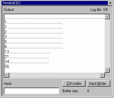
Open the Terminal I/O window and run your application by choosing Debug>Go or clicking the Go button on the toolbar.
The application should stop in the interrupt function.
5
To inspect the contents of the serial communication port receive register UARTRECEIVE, choose View>Register to open the Register window. Choose UART from the drop-down list.
6
Run your application by choosing Debug>Go or clicking the Go button on the toolbar. The application should stop in the interrupt function.
Note how the contents of UARTRECEIVE has been updated.
7
Click Go again to see the next number being printed in the Terminal I/O window.
Because the main program has an upper limit on the Fibonacci value counter, the tutorial application will soon reach the exit label and stop.
The Terminal I/O window will display the Fibonacci series.
Using macros for interrupts and breakpoints
To automate the setting of breakpoints and the procedure of defining interrupts, the system macros __setSimBreak and __orderInterrupt, respectively, can be executed by the setup macro execUserSetup.
The files SetupAdvanced.mac for ARM7TDMI and SetupAdvancedCM3.mac for Cortex-M3 are extended with system macro calls for setting the breakpoint and specifying the interrupt:
For ARM7TDMI (the arm7 dummy device):
simulationSetup()
{...
_interruptID = __orderInterrupt( "IRQ", 4000,
2000, 0, 1, 0, 100 );
 
if( -1 == _interruptID )
{
__message "ERROR: failed to order interrupt";
}
 
_breakID = __setSimBreak( "UARTRECEIVE", "R", "Access()" );
}
For Cortex-M3 (the cm3 dummy device):
simulationSetup()
{...
_interruptID = _ _orderInterrupt( "UART", 4000,
2000, 0, 1, 0, 100 );
 
if( -1 == _interruptID )
{
__message "ERROR: failed to order interrupt";
}
 
_breakID = __setSimBreak( "UARTRECEIVE", "R", "Access()" );
}
If you replace the file SetupSimple.mac, used in the previous tutorial, with the file SetupAdvanced.mac or SetupAdvancedCM3.mac, C-SPY will automatically set the breakpoint and define the interrupt at startup. Thus, you do not need to start the simulation by manually filling in the values in the Interrupts and Breakpoints dialog boxes.
Note: Before you load the file SetupAdvanced.mac or SetupAdvancedCM3.mac you should remove the previously defined breakpoint and interrupt.